Wiring Diagram For a Light Switch
Wiring Diagram For a Light Switch
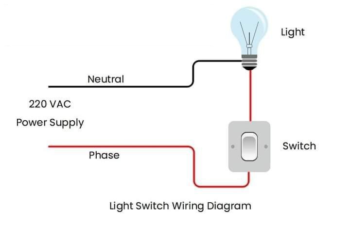
is a wiring diagram for a light switch. It shows how to connect a light bulb to a 220 VAC power supply using a switch and wires. The diagram uses labels and annotations to explain the components and functions of the circuit.
The purpose of this diagram is to illustrate how to wire a light switch and a light bulb using a simple circuit. This diagram can be used as a guide for installing or repairing a light switch in a home or office.
Here are some important points :
Components: The diagram consists of four main components: a light bulb, a switch, a power supply, and wires. The light bulb is the device that produces light when electricity flows through it. The switch is the device that controls the flow of electricity by opening or closing the circuit. The power supply is the source of electricity for the circuit. The wires are the conductors that connect the components and carry the electric current.
Wiring: The diagram shows how the wires are connected to the components. The neutral wire (black) connects the light bulb to the power supply. The phase wire (red) connects the switch to both the power supply and the light bulb. The switch acts as a break in the phase wire, allowing the user to turn the light on or off by flipping the switch.
Labels: used to identify the components and the wire types. The labels are placed near the components or along the wires. The labels help the user to understand the function and role of each component and wire in the circuit.

