Permanent Split Capacitor (PSC) motor Wiring Diagram
Permanent Split Capacitor (PSC) motor Wiring Diagram
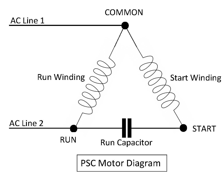
This is diagram of a permanent split capacitor (PSC) motor. Here’s a breakdown of the key elements:
Components:
- AC Line 1 and 2: These represent the incoming power supply to the motor.
- Run Winding and Start Winding: These are the two sets of coils within the motor that generate the magnetic field to create torque.
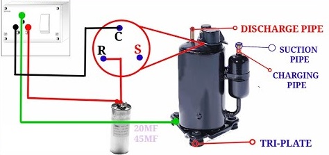
- Run Capacitor: This capacitor helps improve the starting torque and efficiency of the motor.
- Common: This is the connection point between the run winding and the start winding.
Function:
- When AC power is applied, the current flows through both the run winding and the start winding.
- The start winding is designed to have a higher impedance than the run winding, so it initially draws more current.
- This creates a larger phase shift between the currents in the two windings, which produces a stronger starting torque.
- Once the motor reaches a certain speed, a centrifugal switch disconnects the start winding from the circuit.
- The motor then continues to run using only the run winding and the run capacitor.
Analysis:
- PSC motors are known for their simple design and low cost.
- They are commonly used in applications that require high starting torque, such as air conditioners, refrigerators, and compressors.
- However, they are less efficient than other types of motors, such as brushless DC motors.
Additional notes:
- The specific values of the components (e.g., capacitance, inductance) will vary depending on the specific motor application.
- The diagram you sent does not show the centrifugal switch, which is an important part of the PSC motor’s operation.

