Concise and Simple Guide to Resistor Color Coding System
Concise and Simple Guide to Resistor Color Coding System
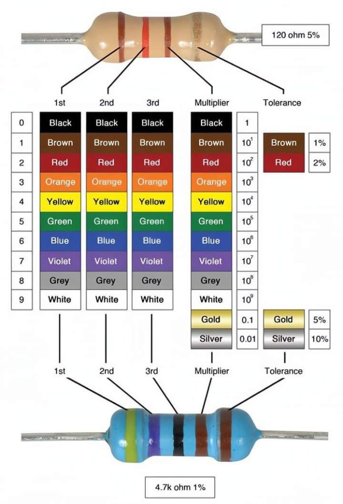
This is a diagram of a resistor and its color coding system used to identify its resistance value.
Resistors are electrical components that control the flow of current in a circuit. The resistance value is measured in ohms (Ω). The color coding system consists of colored bands painted around the body of the resistor. Each color represents a specific digit (0-9) or a multiplier. In the diagram, the first three colored bands represent the first three digits of the resistance value, and the fourth band represents the multiplier. The final band (optional) represents the tolerance of the resistor, which indicates the variation in resistance value compared to the nominal value.
Here’s a breakdown of the resistor color code in the image:
- Band Color | Digit | Multiplier | Tolerance *—|—|—|—|
- Black | 0 | 1 | ±1%
- Brown | 1 | 10 | ±1%
- Red | 2 | 100 | ±2%
- Orange | 3 | 1,000 | ±3%
- Yellow | 4 | 10,000 | ±4%
- Green | 5 | 100,000 | ±0.5%
- Blue | 6 | 1,000,000 | ±0.25%
- Violet | 7 | 10,000,000 | ±0.1%
- Grey | 8 | 100,000,000 | ±0.05%
- White | 9 | 1,000,000,000 | ±0.01%
- Gold | – | 0.1 | ±5%
- Silver | – | 0.01 | ±10%
The bottom right corner of the diagram shows an example of a resistor with color bands. The resistor has a brown, brown, black, and gold band. Following the color code chart, the first brown band represents the digit 1, the second brown band represents the digit 1, the third black band represents the digit 0, and the gold band represents a multiplier of 0.1. Therefore, the resistance value of this resistor is 110 ohms with a tolerance of ±5%.

