Simple Light Switch Wiring Diagram
Simple Light Switch Wiring Diagram
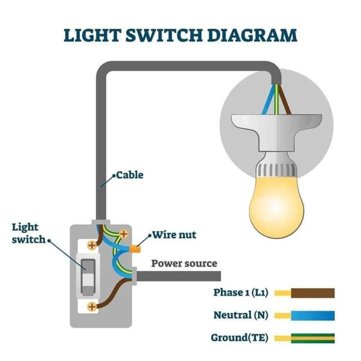
This is a diagram depicting a light switch wiring scheme . Here’s a breakdown of the labeled components and their relationship to each other:
- Light Switch: This is the physical switch that you toggle to turn the light on or off. The diagram shows a single-pole, single-throw switch which means it controls a single light fixture from one location.
- Cable: This represents the electrical cable that supplies power to the circuit and the light fixture.
- Wire Nut: These are small connectors used to join the ends of electrical wires together. In the diagram, the wire nut connects the incoming power cable to the light switch and the outgoing cable to the light fixture.
- Power Source: This signifies the electrical source that supplies power to the circuit. It is typically indicated by a brown wire labeled “Phase 1 (L1)” in the diagram.
- Neutral (N): This represents the neutral wire in the electrical circuit. It usually carries a white wire.
- Ground (TE): This indicates the grounding wire which provides a path for any stray current to flow to the ground in case of a fault. It is typically signified by a green or bare copper wire.
The diagram depicts a very basic electrical circuit for a single light switch controlling a single light fixture. However, it is important to note that electrical work should only be performed by a qualified electrician as there is a risk of serious injury or death if done incorrectly.

